


DOCSIS
DOCSIS Technology: What’s Changed in the Past Year and Why It Matters

Key Points
- DOCSIS 3.1 technologies (including DOCSIS 3.1+ cable modems) have now become the workhorse of the HFC network, enabling multigigabit tiers at scale.
- DOCSIS 4.0 interoperability events and vendor demonstrations have proven 14 Gbps to 16 Gbps aggregate downstream capacity and multivendor interoperability, validating the 10G roadmap on HFC networks.
- New work on a 3 GHz optional annex for DOCSIS 4.0 technology — and research toward 6 GHz — is turning last year’s long-term ideas into concrete steps for the next generation of DOCSIS technology.
DOCSIS® technology continues to evolve at a rapid pace. Cable operators have continued deploying DOCSIS technology and providing high-speed internet services to hundreds of millions of customers around the world. The year 2025 was exciting for cable networks, both in terms of deployments of new technology and continued innovation in the development of technology for the next quarter of a century.
A year ago, our blog post “The Evolution of DOCSIS Technology: Building the Future of Connectivity” walked through how DOCSIS technology evolution fits in the broader connectivity roadmap, and how CableLabs and the cable industry as a whole are already thinking about and working on what comes next. In 2026, the conversation has shifted from what’s theoretically possible to what’s actually happening in the field.
DOCSIS 3.1 Technology: A Decade In and Still Climbing
It’s been a decade since DOCSIS 3.1 technology debuted on the world stage, and cable operators continue to deploy it in all major markets. During that time, operators have upgraded the outside plant to support mid-split and high-split (increased upstream spectrum) technologies across their footprint. In parallel, the networks have transitioned to the Distributed Access Architectures (DAA), replacing older analog nodes with new remote PHY devices (RPDs). DOCSIS 3.1 continues to be a strong competitive technology.
In 2025, DOCSIS 3.1+ cable modems with additional (4+) OFDM channels were certified and are being both chosen and deployed to get even higher downstream speeds on the network. In 2025, DOCSIS 3.1+ cable modems with additional downstream (four or more OFDM) channels were certified; operators are now deploying these channels to achieve even higher downstream speeds on the network.
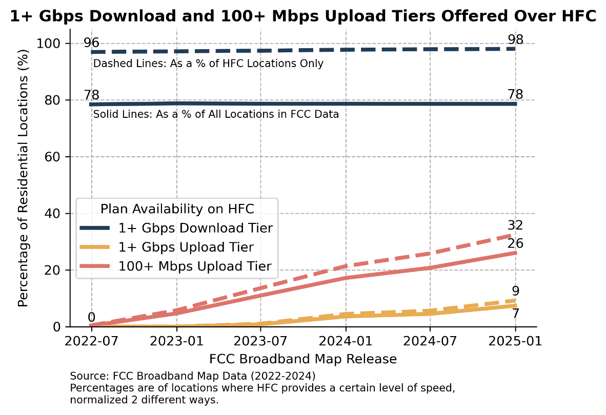
CableLabs’ analysis of FCC National Broadband Map data for the United States (June 2022 through December 2024) shows a strong presence of DOCSIS 3.1 deployments and an accelerating transition to midsplit and highsplit HFC plants. As of December 2024, 98% of all residential locations served by cable operators have access to 1+ Gbps downstream tiers over HFC. Over the same period, the share of locations with access to 100+ Mbps upstream tiers over HFC increased from about 1% to 32%, while 1+ Gbps upstream increased to 9%.
The FCC data analysis and graph below are credited to Jacob Malone, principal strategist and senior director, Network Demand Strategy, CableLabs.
Although multi-gigabit speeds are important, user experience increasingly comes down to latency, consistency and responsiveness — especially for cloud gaming, collaboration tools and immersive applications. That’s where Low Latency DOCSIS (LLD), introduced in DOCSIS 3.1 (and carried forward into DOCSIS 4.0), plays a key role. Operators such as Comcast have made strides in deploying this technology to enable a low-lag connectivity experience for their customers.
At the same time, improving network reliability has become a major focus of cable operators worldwide. Using data from the network, tools such as Profile Management Applications (PMA) and Proactive Network Maintenance (PNM) have become a vital part of network operations by maintaining connectivity, identifying issues and ultimately reducing downtime, as networks push toward higher utilization and complex channel configurations.
DOCSIS 4.0 Technology: From Interop Milestones to Deployment Readiness
Now let’s talk about DOCSIS 4.0, starting with interoperability events and multi-vendor readiness. Over the past year, interoperability events have moved from early experimentation to demonstrating performance and interoperability at scale.
At the June 2025 DOCSIS 4.0 Interop, multiple CCAP cores, RPDs and cable modems from various suppliers operating together in a distributed access architecture, were able to achieve downstream DOCSIS throughput reaching 14 Gbps across a multi-vendor network. A few months later, at the August DOCSIS 4.0 and DAA Technology Interop event, vendors showcased record-setting setups built on that foundation, demonstrating 16.25 Gbps downstream throughput across two load-balanced DOCSIS 4.0 modems. Demonstrations at SCTE Tech Expo’25 showed 2x2 DOCSIS 4.0 RPDs enabling unprecedented capacity.
Beyond the speed records, these results confirm that DOCSIS 4.0 can comfortably achieve 10G-class downstream performance over the HFC network; that multi-vendor interoperability of CCAP cores, RPDs and cable modems is real, and that virtualized, cloud-native CMTS platforms are a key part of the DOCSIS 4.0 story. Upstream speeds up to 3 Gbps and 5.5 Gbps were also demonstrated in different configurations. Taken together, these accomplishments validate the 10G roadmap that the cable industry has laid out and give operators confidence that DOCSIS 4.0 can compete head-to-head with fiber in both performance and operational flexibility.
Operators are in various stages of assessing and testing outside plant components and equipment, ultimately to support the upgrade to DOCSIS 4.0-based services. Over the last year, most operators in their individual labs have been evaluating various equipment. This includes outside plant components, such as taps, passives, and amplifiers, along with RPDs, CCAP cores, and cable modems needed for DOCSIS 4.0 deployments. Some operators are beginning to deploy these components into the network, outside plant components first (e.g., the smart amplifiers), then DOCSIS 4.0 RPDs and CCAP cores, and ultimately the cable modems to the customer homes, along with any necessary passive component upgrades. Deployments enabling the full duplex mode of operation have already seen great success, and the stage is set for successful deployments of frequency division duplex mode of operation as well.
This year, it’s going to be exciting to see these DOCSIS 4.0 deployments begin to scale around the world.
But wait, there’s more!
In 2026 and Beyond: Extending DOCSIS 4.0 to 3 GHz — and Looking to 6 GHz
CableLabs CEO Phil McKinney announced at SCTE TechExpo25 that CableLabs will begin industry work focused on enabling the HFC network to support DOCSIS data transmission up to 3 GHz. This extension can enable up to 25 Gbps of aggregate capacity — a leap that positions HFC networks not just to meet demand, but to stay well ahead of it.
The 3 GHz specification work has since begun with wide industry participation from both the cable operator side and the vendor community. This includes technologists from operators’ engineering organizations, CM vendors, silicon vendors, RPD manufacturers, CCAP core suppliers, along with outside plant component folks such as amplifier vendors, taps and passives manufacturers, et al. The work includes analyzing the plant models and characteristics of the network at higher frequencies and understanding the ability to build outside plant components to support high-fidelity operations at these higher frequencies. As we get agreement on these analyses, a new optional annex will be developed and added to the DOCSIS 4.0 specifications. The extension of the spectrum will allow DOCSIS signals to use the 1.8 GHz to 3GHz frequency range, opening up spectrum for additional downstream OFDM channels. The goal is to make these 3GHz requirements a part of the current DOCSIS 4.0 technology as an optional annex and enable the choice for the operators and vendors to test, develop and deploy interoperable solutions with these enhanced capabilities in markets that need them.
As McKinney also discussed at TechExpo, CableLabs and thought leaders in the industry are analyzing and evaluating the potential of HFC networks all the way to 6 GHz. This expansion could ultimately provide up to 50 Gbps of aggregate capacity and open the door to exciting new use cases that leverage the HFC networks we have today. This research is happening in the background, with various analyses on plant characteristics, tap design, amplifier design, and analysis of HFC network upgrade paths. Once the fundamental building blocks for transmission up to 6 GHz are validated, the technology development and specification work for another leap in DOCSIS capability can begin.
Connecting Past, Present and Future
Taken together, these developments extend the cable technology arc further:
- The past, DOCSIS 3.1 technology, has established a solid, backward-compatible foundation that brought gigabit speeds to market and prepared the HFC plant for higher splits and DAA.
- The present, defined by DOCSIS 4.0 technology, is where operators are beginning to deploy multigigabit services, validating 10G-class performance and building multivendor, virtualized networks.
- The future is now anchored in concrete work on a 3 GHz extension to DOCSIS 4.0 solutions and early planning for 6 GHz operation, ensuring that DOCSIS technology has a roadmap well beyond today’s generation.
It’s an exciting time to be working on HFC and DOCSIS technologies. The past year has shown that the industry is not only keeping pace with demand but actively shaping what the next decades of cable broadband will look like — from the networks already in the field to the specifications and research that will power the internet of the future.
DOCSIS
The Evolution of DOCSIS Technology: Building the Future of Connectivity

Key Points
- Each new generation of DOCSIS®️ technology has enabled operators to deliver higher speeds, increased capacity, lower latency and more robust security.
- DOCSIS networks are designed with backward compatibility that allows older modems to operate alongside newer devices.
- CableLabs owns the DOCSIS trademark and — along with its working groups and members — oversees the development of all new versions of DOCSIS technology.
A fundamental enabler in connecting people around the globe, DOCSIS technology has empowered millions to live, work, learn and play. Since the days of the first DOCSIS 1.0 cable modems (CMs) almost 30 years ago, DOCSIS technology has continued to evolve, benefitting from a robust ecosystem of operators and vendors working together with CableLabs to develop technologies that enable differentiated services.
Just in the last decade, operators have moved from DOCSIS 3.0 technology to deploying DOCSIS 3.1 technology at scale. Now, in 2024 and going into 2025, operators are evaluating, starting initial deployments and rolling out DOCSIS 4.0 networks.
Because DOCSIS networks always provide backward compatibility, older modems can coexist and provide service to customers even after the operator has moved ahead to newer technology. This is critical as modems often live in the network for many years.
Work at CableLabs is underway to define the future of DOCSIS networks and the technology’s role in our broader network strategy. For a better understanding of what’s ahead, let’s discuss some of the recent evolutionary steps in the DOCSIS technology ecosystem.
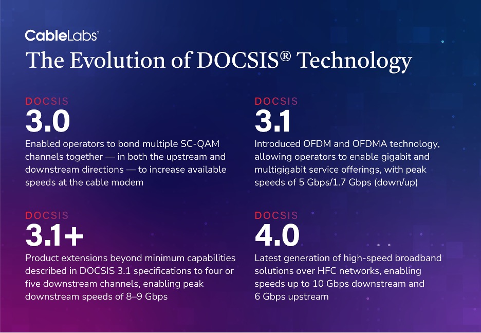
What Is DOCSIS 3.0?
DOCSIS 3.0 networks introduced channel bonding and allowed operators to bond multiple single carrier quadrature amplitude modulation (SC-QAM) channels together (in both the upstream and downstream directions) to increase the available speeds at the CM. A DOCSIS 3.0 CM with 32 SC-QAM channels in the downstream and four SC-QAM channels in the upstream could theoretically get a peak throughput of 1 Gbps/100 Mbps (downstream/upstream) on the network, though actual service tiers offered on individual networks may have differed.
What Is DOCSIS 3.1?
DOCSIS 3.1 technology introduced orthogonal frequency division multiplexing (OFDM) and orthogonal frequency division multiple access (OFDMA) technology. A DOCSIS 3.1 CM, typically with two OFDM channels and 32 SC-QAM channels in the downstream and two OFDMA channels and four SC-QAM channels in the upstream, theoretically would get to a throughput of 5 Gbps/1.7 Gbps on the network. Actual service tiers offered by operators would be dependent on their network configuration and channels and service tiers enabled.
DOCSIS 3.1 technology allowed operators to enable gigabit and multigigabit service offerings (downstream) in their markets. Depending on the operator upgrades to their outside plant, the upstream capacities could range from 100 to 250 Mbps on a low-split plant, to 250 to 575 Mbps on a mid-split plant, to 1.5 to 1.7 Gbps on a high-split plant.
What Is DOCSIS 3.1 Plus?
In the last year, vendors have built DOCSIS 3.1 cable modems with additional downstream channel capabilities, going up from two, to four or even five OFDM channels. This is a welcome product extension beyond the minimum device capabilities described in the DOCSIS 3.1 specifications.
CableLabs, along with our member operators in the industry and NCTA, are coalescing around the term DOCSIS 3.1 Plus (DOCSIS 3.1+) CM to identify this new class of modems. DOCSIS 3.1 Plus CMs will enable up to 8 or 9 Gbps on the downstream — again, depending on the spectrum available in the cable plant for an operator. Typically, a software upgrade is needed on the CMTS to enable the additional channels. Alternatively, an operator can also seed the network with DOCSIS 4.0 CMs, which have a minimum of five OFDM channels, on existing DOCSIS 3.1 CMTS to support similar increases in downstream speeds.
What Is DOCSIS 4.0?
DOCSIS 4.0 technology is the latest generation of high-speed broadband solutions over hybrid fiber coax (HFC) networks. DOCSIS 4.0 technology catapults the broadband network speeds up to 10 Gbps downstream and 6 Gbps upstream.
DOCSIS 4.0 specifications build on the OFDM and OFDMA technology. It increases the spectrum available for the upstream and downstream and then fills them with more OFDM and OFDMA channels. The technology allows different outside plant upgrade paths to operators, a frequency division duplex (FDD) mode or a full duplex (FDX) mode of operation. For FDD mode, there are different upstream/downstream splits an operator can choose for their outside plant, each providing an increase in upstream/downstream capacity. FDX mode also enables flexibility in how operators size and utilize the FDX portion of the spectrum to meet the needs of their customers.
In an FDD plant, for an FDD CM, the upstream capacities could range from 4.2 Gbps (on a UHS-396 MHz plant), to 6 Gbps on a (UHS-684 MHz plant) and the downstream capacities could range from 9-10 Gbps. In an FDX plant, an FDX CM also can reach up to 6 Gbps on the upstream and 9-10 Gbps or more on the downstream. This is assuming a DOCSIS 4.0 CM has the required minimum support for five OFDM downstream channels and seven OFDMA channels. A CM with more channels and on a plant where the additional spectrum is enabled could get downstream speeds beyond 10 Gbps.
Current product developments also enable devices that can operate on both types of networks — either FDD or FDX (albeit not at the same time, as the outside plant will be configured for either one mode of operation or the other). In addition, a DOCSIS 3.1 CM can also be software upgraded to participate in an FDX network, known as an FDX-Limited or an FDX-L CM, with limited capabilities for operating within the FDX band. Though this CM’s peak speeds remain the same, it allows operators to use the FDX spectrum flexibly, for both DOCSIS 3.1 CMs and DOCSIS 4.0 CMs.
The DOCSIS Technology Evolution
CableLabs has hosted nine DOCSIS 4.0 Interop·Labs events since July of 2023, and more are planned for 2025. Each event offers a new, up-close look into how DOCSIS 4.0 equipment is maturing. Operators are busy evaluating and testing the different components that will need to be upgraded for a DOCSIS 4.0 network — taps, amplifiers, RPDs, CCAP cores and modems.
The industry remains focused on implementing and deploying the DOCSIS 4.0 technology into the broadband networks. Large-scale deployment of DOCSIS 4.0 technology will bring customers into the 10G era in the near future.
So, what's next? What will the next generation of DOCSIS technology look like?
Continuing Industry Collaboration
As we shift from the Speed Era into the Experience and Adaptive eras — an evolution highlighted in CableLabs’ Technology Vision — DOCSIS technology will continue to evolve as well. The cable operator community, the vendor community and CableLabs have all been thinking and conducting research on how DOCSIS networks should move forward for the next big leap in broadband technology.
There is much work to be done to define new generations of DOCSIS technology and what it will truly look like. As always, CableLabs — which owns the DOCSIS trademark — will work closely with its members and working groups to oversee the development of future versions of the technology.
The impact to the outside plant and the physical characteristics of the coax are important considerations. The technology development work will include analysis and decisions on the spectrum range we ultimately target (for example, 3 GHz or 6 GHz or 7 GHz), where the upstream/downstream/full duplex regions will be, as well as what the underlying physical layer technology (fidelity requirements, channel sizes, FEC, etc.) and what the potential MAC layer technology improvements are going to be.
It’s an exciting time to be in the connectivity business! CableLabs looks forward to collaborating with the ecosystem on future developments for DOCSIS technology.
Follow the CableLabs blog to stay up to date on these developments and our Interop·Labs events.
Networks
Increase Upstream Reliability and Capacity with Optimized Profiles

Network usage patterns have shifted in unprecedented ways in the last few months with vast swaths of the population staying at home. A substantial increase in network traffic has been observed from homes with people collaborating for work and children learning over the Internet with online school sessions and material. The access networks have seen a transition of the peak weekend levels of traffic become the new normal throughout the week.
In this time of network traffic increase, reliability and capacity are increasingly important. Upstream reliability is fundamental to the network experience as seen by the end user in the home. For DOCSIS 3.1 and 4.0 networks configuring profiles is the key to maintaining a reliable channel while simultaneously optimizing capacity. Profiles define the modulation orders used on the channel, with higher modulation orders allowing for more bits of information to be communicated per modulation symbol.
In a previous blog post, we discussed downstream profile management. In this blog, we focus on upstream profile management which differs from the downstream due to the structure of the Hybrid-Fiber-Coax (HFC) plant and the nature of bursty transmissions from a cable modems (CM).
In the downstream direction, there is one location from where the signals enter the HFC plant, specifically the cable modem termination system (CMTS) in the headend. The operator has control of the signal at that point and along the network, to ensure it reaches every CM. From the head end to the CM, the RF signal fans out in a star topology network in a point to multipoint (P2MP) fashion. It is the opposite on the upstream/return path: the RF signals enter the plant from every home that is attached to the plant, and all of those signals combine together as they travel to the headend. Typical of all P2MP networks, the noise from every device on the network gets combined as it travels upstream and is finally received on the upstream port at the CMTS. This is known as the noise funneling problem, as shown in the diagram below. Thermal noise at the amplifiers and fiber optic link noise are common sources of upstream noise. Other noise sources which ingress into the upstream path include impulse noise from loose connectors, unterminated splitters or taps, cracked cables, common path distortion due to corroded connectors, clipping distortion etc.
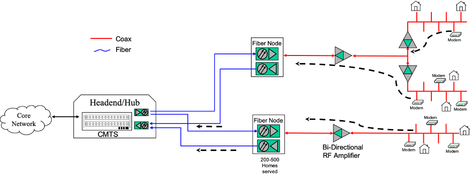
Simple HFC diagram showing US Noise funneling
Thus, in the upstream, the noise from every house and every network element gets accumulated and is seen at the upstream receiver on the CMTS. Now a CMTS receiver can measure the received modulation error ratio (RxMER) for each CM, see some example measurements from a live network in the diagram below. In the upstream, this signal to noise signature for each of the CMs (that are sharing the upstream channel) starts looking very similar, as they all share the same noise across the channel with slight differences due to the signal levels itself. This means common profiles can be designed for many CMs experiencing similar noise conditions. Most CMs will be able to use a common profile. For CMs which suffer more noise, they can be put into a different profile optimized for their particular noise environment. The modulation orders within a profile can vary appropriately across the spectrum as per the noise levels in that part of the spectrum.
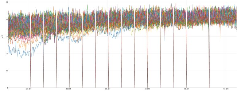
Upstream measured RxMER for CMs on a D3.1 OFDMA channel (Data from a European Operator)
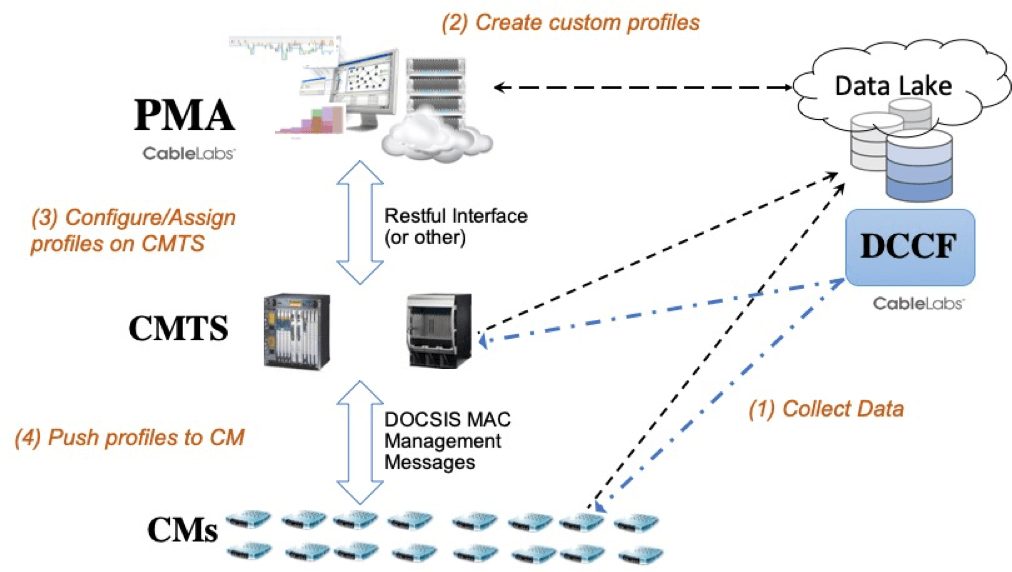
The upstream Profile Management Application (PMA) can automate this design of the profiles on various upstream channels across various segments in the cable plant. Reading the upstream RxMER from the CMTSs on the network, processing the RxMER information with intelligent algorithms to create profiles, and then configuring the newly optimized profiles on the CMTS are the primary functions an upstream PMA solution accomplishes. Configuring optimized profiles brings solid reliability to the upstream network connection and also increases the capacity in parts of the spectrum which can accommodate higher modulation orders.
Many cable operators across the world are now turning on upstream OFDMA channels and leveraging the upstream PMA capability to automate the creation of profiles for their D3.1 upstream OFDMA channels.
If you are interested in discovering more details about upstream or downstream PMA, or setting up a field trial, please feel free to contact us to receive more in-depth information.

10G
CableLabs Low Latency DOCSIS® Technology Launches 10G Broadband into a New Era of Rapid Communication

Remember the last time you waited (and waited) for a page to load? Or when you “died” on a virtual battlefield because your connection couldn’t catch up with your heroic ambitions? Many internet users chalk those moments up to insufficient bandwidth, not realizing that latency is to blame. Bandwidth and latency are two very different things and adding more bandwidth won’t fix the internet lag problem for latency-sensitive applications. Let’s take a closer look at the difference:
- Bandwidth (sometimes referred to as throughput or speed) is the amount of data that can be delivered across a network over a period of time (Mbps or Gbps). It is very important, particularly when your application is trying to send or receive a lot of data. For example, when you’re streaming a video, downloading music, syncing shared files, uploading videos or downloading system updates, your applications are using a lot of bandwidth.
- Latency is the time that it takes for a “packet” of data to be sent from the sender to the receiver and for a response to come back to the sender. For example, when you are playing an online game, your device sends packets to the game server to update the global game state based on your actions, and it receives update packets from the game server that reflect the current state of all the other players. The round-trip time (measured in milliseconds) between your device and the server is sometimes referred to as “ping time.” The faster it is, the lower the latency, and the better the experience.
Latency-Sensitive applications
Interactive applications, where real-time responsiveness is required, can be more sensitive to latency than bandwidth. These applications really stand to benefit from technology that can deliver consistent low latency.
As we’ve alluded, one good example is online gaming. In a recent survey we conducted with power users within the gaming community, network latency continually came up as one of the top issues. That’s because coordinating the actions of players in different network locations is very difficult if you have “laggy” connections. The emergence of Cloud gaming makes this even more important because even the responsiveness of local game controller actions depends on a full round-trip across the network.
Queue Building or Not?
When multiple applications share the broadband connection of one household (e.g. several users performing different activities at the same time), each of those applications can have an impact on the performance of the others. They all share the total bandwidth of the connection, and they can all inflate the latency of the connection.
It turns out that applications that want to send a lot of data all at once do a reasonably good job of sharing the bandwidth in a fair manner, but they actually cause latency in the network when they do it, because they send data too quickly and expect the network to queue it up. We call these “queue-building” applications. Examples are video streaming and large downloads, and they are designed to work this way. There are also plenty of other applications that aren’t trying to send a lot of data all at once, and so don’t cause latency. We call these “non-queue-building” applications. Interactive applications like online gaming and voice connections work this way.
The queue-building applications, like video streaming or downloading apps, get best performance when the broadband connection allows them to send their data in big bursts, storing that data in a buffer as it is being delivered. These applications benefit from the substantial upgrades the cable industry has made to its networks already, which are now gigabit-ready. These applications are also latency-tolerant – user experiences are generally not impacted by latency.
Non-queue-building applications like online gaming, on the other hand, get the best performance when their packets don’t have to sit and wait in a big buffer along with the queue-building applications. That’s where Low Latency DOCSIS comes in.
What is Low Latency DOCSIS 3.1 and how does it work?
The latest generation of DOCSIS that has been deployed in the field—DOCSIS 3.1—experiences typical latency performance of around 10 milliseconds on the access network link. However, under heavy load, the link can experience delay spikes of 100 milliseconds or more.
Low Latency DOCSIS (LLD) technology is a set of new features, developed by CableLabs, for DOCSIS 3.1 (and future) equipment. LLD can provide consistent low latency (as low as 1 millisecond) on the access network for the applications that need it. The user experience will be more consistent with much smaller delay variation.
In LLD, the non-queue-building applications (the ones that aren’t causing latency) can take a different path through the DOCSIS network and not get hung up behind the queue-building applications. This mechanism doesn’t interfere with the way that applications go about sharing the total bandwidth of the connection. Nor does this reduce one application's latency at the expense of others. It is not a zero-sum game; rather, it is just a way of making the internet experience better for all applications.
So, LLD gives both types of applications what they want and optimizes the performance of both. Any application that wants to be able to send big bursts of data can use the default “classic” service, and any application that can ensure that it isn’t causing queue build-up and latency can identify its packets so they use the “low latency” service. Both then share the bandwidth of the broadband connection without one getting preference over the other.
Incorporating LLD Technology
Deploying Low Latency DOCSIS in a cable operator’s network can be accomplished by field-upgrading existing DOCSIS 3.1 CMs and CMTSs with new software. Some of the low latency features are even available to customers with older (pre-DOCSIS 3.1) CMs.
The technology includes tools that enable automatic provisioning of these new services, and it also introduces new tools to report statistics of latency performance to the operator.
Next Steps
DOCSIS equipment manufacturers are beginning to develop and integrate LLD features into software updates for CMTSs and CMs, and CableLabs is hosting Interoperability Events this year and next year to bring manufacturers together to help iron out the technology kinks.
We expect these features to become available to cable operators in the next year as they prepare their network to support low latency services.
LLD provides a cost-effective means of leveraging the existing hybrid fiber-coaxial (HFC) network to provide a high-performance network for latency-sensitive services. These services will help address customers’ requirements for many years into the future, maximizing the investments that cable operators have made in their networks. The cable industry is provisioning the network with substantial bandwidth and low latency to take another leap forward with its 10G networks.
For those attending the SCTE Cable-Tec Expo in New Orleans, Greg will be presenting the details of this technology on a SCTE panel “Low Latency DOCSIS: Current State and Future Vision”

Wired
The Profile Management Application: Optimizing DOCSIS® 3.1 Networks

Cable operators are broadly deploying DOCSIS 3.1 technology around the world. Operators in North America and Europe have announced gigabit service offerings that use the technology across their footprint. In this blog, I focus on techniques by which operators can boost the capacity and robustness of their existing DOCSIS 3.1 network.
Introducing Toolsets for Optimizing the DOCSIS 3.1 Network
DOCSIS 3.1 specifications introduced orthogonal frequency division multiplexing (OFDM) technology to the access network. In DOCSIS 3.0 and prior technologies, a single-carrier downstream channel (6 MHz) would be configured with just the one modulation order (say, 256-QAM). The DOCSIS 3.1 technology divides a wider (e.g. 192 MHz) channel into a number of small subcarriers spaced at 25 kHz or 50 kHz apart, creating up to 7600 subcarriers. These subcarriers can be individually configured to operate at a different modulation order, anywhere from 256-QAM, to 1024-QAM, all the way to 4096-QAM.
A specific configuration of modulation orders for every subcarrier in the OFDM channel is known as a “profile.” A cable modem termination system (CMTS) can use multiple profiles on a channel; profiles differ in the modulation orders assigned to each subcarrier.
 Different modems experience the network in different ways. Some modems may have a noisier environment, whereas others see a relatively clean plant. The figure shows an example of the interference seen by a modem in part of the OFDM channel.
Profiles allow the channel to operate at a higher modulation order in clean parts of the spectrum and then go down to more robust modulation orders when there is any interference present. The idea with multiple profiles is to have the CMTS use different profiles for such different groups of cable modems. This allows the operator to reach two goals:
- minimize transmission errors on the network and
- maximize network capacity.
The same concept applies to upstream OFDMA channels, where one can create upstream profiles for the channel, to increase reliability and throughput.
The Profile Management Application (PMA) Solution
If there are say 4 OFDM channels per port, 10 ports per line-card, and 10 line-cards on a CMTS, then there could be easily over a couple of million subcarriers requiring a specific configuration! This represents an immense configuration challenge which cannot be solved manually. This problem is made more difficult because profiles are not typically “one size fits all,” but rather they need to be tailored to the set of cable modems on the channel, the interference on the channel, and they also need to adjust to plant changes over time. The question then becomes: What is the most efficient method for automating the creation of multiple profiles to maximize robustness and capacity?
I am pleased to announce that CableLabs has met this tremendous challenge with the introduction of the Profile Management Application (PMA). The PMA creates a set of optimal profiles for each channel and assigns profiles to modems. And the PMA accomplishes this dynamically by proactively reading data collected from the network. The PMA can create optimized modulation profiles periodically, as well as backup profiles in case of errors. It can also intelligently decide when to roll out profile changes to the network. A single PMA instance can create and configure profiles for a number of CMTSs in a short period of time and help the operator understand the data capacity of each channel.
How It Works—PMA Architecture and Algorithms
CableLabs released a PMA Technical Report that describes the PMA architecture, use cases, and interface definitions. We also developed data models (YANG) and protocols to facilitate the design of a software application to configure and manage modulation profiles.
Determining the optimal set of modulation profiles to use on a DOCSIS 3.1 channel is a task for intelligent software, given the number of modems, the number of subcarriers and the differences in signal quality across the channel each modem experiences. This CableLabs paper on profile management algorithms describes methods to optimally compute the profiles. The paper also introduces a metric indicating the capacity gain a set of profiles obtains compared with running all traffic at 256-QAM. The key idea is to use clustering algorithms to group modems that have similar signal-to-noise signatures across the channel and then design a profile for each group. The PMA algorithm searches for the best set of profile definitions to maximize the overall capacity and at the same time keeps the individual profiles robust to observable interference patterns.
Some of the information that a PMA needs to compute the profiles includes the channel information from a CMTS, list of modems and network signal quality metrics (mainly, each modem’s per subcarrier RxMER data). Also using performance data (e.g., codeword error rates), a PMA can further refine the profiles.
How It Works—Deployment
A PMA field deployment would include the following:
- Data Collection: A centralized server is needed for modems and CMTSs to upload signal quality data. Operators can use the CableLabs DOCSIS Common Collection Framework (DCCF) to implement this.
- PMA: Using the data collected, this application creates optimized profiles per channel. It configures these profiles on the CMTS, assign CMs to profiles and can initiate performance tests.
- CMTS: Configures profiles for the individual channels, assigns the modulation profiles to CMs and ultimately sends/receives data using the profiles.
- CMs: Cable Modems use the profiles defined and assigned by the CMTS to receive/send data.
What’s Next? PMA Software Available
CableLabs has developed network-deployable software that operators can integrate and use within their DOCSIS 3.1 access network. This PMA solution can use the data generated by the network devices and create optimized OFDM/OFDMA profiles while considering different capabilities supported across CMTS platforms. The software is capable of calculating profiles for a channel with around 200 CMs in ~30 msecs using a single CPU process, so it is easily scalable across an operator’s network. Many operators are testing and planning PMA deployment using this solution framework. PMA is available via CableLabs C3. Contact us to try it out. (Watch for an upcoming video blog on this topic.)
Gains from PMA
A PMA will help increase the throughput per cable modem and maximize network capacity by optimizing the bit-loading of the subcarriers within a channel. Designing profiles around noisy areas in the plant make the system operation more robust. The bandwidth gains in running a well-designed set of profiles can be anywhere from 15% to 40% capacity increase on a channel, compared with running the whole channel at 256-QAM. This can translate to a solid 200 to 400 Mbps extra capacity on each OFDM channel! This enables an operator to match growing bandwidth demands and defer potential node-splits and new equipment costs.
With this profile management technology, operators can realize the full potential of their DOCSIS 3.1 network, by minimizing transmission errors and maximizing the data capacity of the OFDM/OFDMA channels.
Subscribe to our blog to learn more about PMA in the future.

DOCSIS
Full Duplex DOCSIS® Technology Gets MAC Layer Support

Full Duplex (FDX) DOCSIS® (now a part of DOCSIS 4.0 technology) is an update to DOCSIS 3.1 specifications that builds on the core Orthogonal Frequency Division Multiplexing (OFDM) technology. This additional set of features significantly increases upstream capacity and allows for the same spectrum to be used as downstream or upstream.
The set of MAC Layer technology changes to support FDX DOCSIS has now been incorporated into the next version of the DOCSIS 3.1 MULPI specification. This supports the PHY layer FDX functionality introduced last October. The new FDX DOCSIS capability and functions are introduced as changes across the MULPI (MAC and Upper Layer Protocols Interface) specification and is now an official part of the specification. This important milestone is the result of a great deal of work by CableLabs members, vendors and employees during the past year, and we take this opportunity to acknowledge their valuable contribution to the cable industry.
New MAC Layer Functionality Introduced
The MAC layer functionality introduced supports the new FDX DOCSIS operation on the hybrid-fiber-coax (HFC) link. It is focused on MAC management messaging and operation needed to enable FDX DOCSIS between the CMTS (Cable Modem Termination System) and CM (Cable Modem). This includes FDX DOCSIS channel acquisition/initialization process by a CM, and new processes such as Sounding, Echo Cancellation training, and Resource block assignment.
How it Works – Cable Modem to CMTS Communication
An FDX DOCSIS CMTS will simultaneously receive and transmit in the same FDX DOCSIS spectrum, while FDX DOCSIS (now a part of DOCSIS 4.0 technology) CMs can either receive or transmit in the same FDX DOCSIS spectrum. Thus, communication is full duplex from the perspective of the CMTS but frequency division duplex from the perspective of the CM.
The FDX DOCSIS band is divided into sub-bands and the CMTS assigns which sub-band(s) each CM uses for upstream or downstream operation. This is referred to as a resource block assignment (RBA). Different CMs will have different bandwidth demand for both the upstream and downstream directions which can change over time, and FDX DOCSIS allows for the RBA to be changed dynamically.
A sounding method is used to identify groups of CMs, called Interference Groups (IGs), that would interfere with each other if they were allowed to transmit and receive at the same time in a sub-band. IGs are grouped together into a small number of Transmission Groups (TGs), CMs in the same TG either transmit or receive on any given sub-band and time, as signaled by the CMTS in the RBA. CMs from different TGs have enough isolation to transmit and receive at the same time in the same sub-band.
FDX DOCSIS uses a combination of interference cancellation and intelligent scheduling at the CMTS. On the CM, in order to prevent upstream transmissions from interfering with adjacent downstream channels in the FDX band, echo cancellation techniques are used.
What’s Next for the Full Duplex DOCSIS Technology?
As the FDX DOCSIS specifications mature, we will start to see products with full-duplex capabilities over the next year as silicon designs become available and are incorporated into product designs. In an effort to increase the pace of product development, CableLabs has announced a series of FDX DOCSIS Interoperability events , starting in February. These will start from basic node level echo cancellation and gradually progress into full-blown product interoperability.
The collaborative model at CableLabs for developing common cable industry specifications minimizes interoperability issues and gets the best in class features into the specifications. This accelerates time to market for a product, with the operator getting to deployment faster, and ultimately the consumer gets to reap the benefits of the latest technology.
In the meantime, the big wheels of CableLabs specification work continue to turn:
- We are developing the OSS (Operations Support Systems) changes needed to support FDX DOCSIS.
- We have initiated work for the changes needed to support FDX DOCSIS within the Remote PHY realm. (FDX, now a part of DOCSIS 4.0 technology, assumes a distributed architecture and a plant which supports a node plus zero actives due to the CMTS node echo cancellation functionality)
- As suppliers build the FDX DOCSIS products, the feedback loop into the FDX (now a part of DOCSIS 4.0 technology) specifications remains open and the PHY & MAC specifications continue to be refined.
Full Duplex DOCSIS significantly increases upstream capacity on the HFC network, allows flexible splits of upstream and downstream capacity, and enables cable operators to deploy multi-gigabit symmetrical services. With all the innovations being developed by the industry, it is a great time to be a consumer of high-speed data services over cable.
Karthik Sundaresan is a Principal Architect at CableLabs responsible for the development and architecture of cable access network technologies. He is primarily involved in the DOCSIS family of technologies and their continued evolution.
Subscribe to our blog to stay current on Full Duplex DOCSIS technology (now a part of DOCSIS 4.0 technology).
DOCSIS
New Open Source Initiative at CableLabs

Open source software continues to make solid inroads in the world of network technology. There are various open source industry efforts which are becoming de-facto standards that are being adopted by operators and equipment manufacturers (Linux, Apache, OpenStack, Docker etc). Open source leads to free and quick proliferation of good ideas. Collaboration tackles tough problems which may not be solved individually. The open source approach facilitates a rapid prototyping for new technologies and allows improvement on the most important features. It also allows communities to form around a common cause.
CableLabs is increasing its focus on game-changing innovations and accelerating the delivery of unique competitive advantages to the global cable industry with its CableLabs 2.0 initiative. As a part of this focus, CableLabs would like to announce a new major open/community source project for the cable industry. CableLabs and Cisco are initiating a new collaborative project called ‘OpenRPD’ to develop software which can be used by the industry to build a Remote PHY Device. Cisco will be contributing their Remote PHY interface software to this effort, which forms a baseline on which this project will build. (See Cisco's press release.)
Over the past year, CableLabs, along with our member and vendor community, has worked on the different Distributed CCAP Architectures including Remote PHY and Remote MAC-PHY Architectures. The Remote PHY technology allows for an integrated CCAP to be separated into two components: the CCAP Core and the Remote PHY Device (RPD). The RPD allows all the PHY layer components of a CCAP to be moved out as a separate device into the fiber node in the field.
Remote PHY is a big transition in the traditional access network architecture. To meet the deployment needs of the operators, it is imperative we move the ecosystem quickly. The OpenRPD software effort allows us to do this by enabling faster development of RPD products. We believe that open source software is becoming the new way to create specifications, the mantra now is to ‘write code’ not documents.

A collaborative effort allows for greater reliability in software products, while offering a greater level of security, both of which are important to an RPD platform which will be out in the field. Developing a common code base for some of the basic RPD functions creates a software platform which will minimize interoperability issues between the CCAP-Core and the RPD. It enables companies to focus on their added value and accelerates time to market for a product. This creates a scenario in which everybody wins and the operator gets to deployment of technology faster.
We welcome all interested developers within the CableLabs community to participate in this project. If you would like to participate in the CableLabs OpenRPD Software initiative, please contact me.
May the source be with you.
Karthik Sundaresan is a Principal Architect at CableLabs responsible for the development and architecture of cable access network technologies. He is primarily involved in the DOCSIS family of technologies and their continued evolution.
DOCSIS
CableLabs® New Remote PHY Specifications expand DOCSIS® Network deployment options

DOCSIS technology continues to extend the usefulness of the hybrid fiber coaxial network and increase its global adoption. Distributed Architectures for DOCSIS networks are emerging that provide significant scale advantages and flexible deployment options supporting for both DOCSIS 3.0 and DOCSIS 3.1 networks. Distributed DOCSIS deployments are beginning today in some markets based on the earlier C-DOCSIS specifications.
New Specification Release
CableLabs is documenting several different Distributed CCAP Architectures (including Remote PHY and Remote MAC-PHY) and will release the set of technical reports and specifications throughout this summer.
Last month, CableLabs publicly issued the Remote PHY family of specifications. Theses specifications are also known as MHAv2 as these are an evolution from the original Modular Headend Architecture specifications.
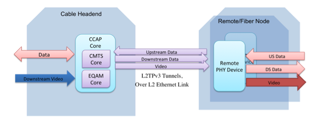
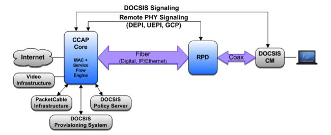
The Remote PHY technology allows for an integrated CCAP to be separated into two components: the CCAP Core and the Remote PHY Device (RPD) and describes the interfaces between them. One of the common locations for an RPD is the optical node device that is located at the junction of the fiber and coax plants, while the CCAP Core stays at the headend. A CCAP core can control and setup data paths with multiple RPDs situated in multiple fiber nodes.
What is Remote PHY?
The Remote PHY technology uses pseudowires between a CCAP Core and a set of RPDs. The CCAP Core contains both a CMTS Core for supporting DOCSIS data transport and an Edge QAM Core for supporting video transport. The CMTS Core contains the DOCSIS MAC (signaling functions, downstream and upstream bandwidth scheduling, and DOCSIS framing) and the upper layer protocols. Remote PHY supports both DOCSIS 3.0 & 3.1 Specifications. The EQAM Core contains all the video processing functions that an EQAM provides today.
The RPD contains mainly PHY related circuitry, such as downstream QAM and OFDM modulators, upstream QAM and OFDM demodulators, together with pseudowire logic needed to connect to the CCAP Core. The RPD platform is a physical layer converter device whose functions are to convert downstream DOCSIS data, MPEG video and out-of-band (OOB) signals received from a CCAP Core over a digital fiber network such as Ethernet or passive optical network (PON) to analog RF for transmission over the coaxial cable; and to convert upstream RF DOCSIS, and OOB signals received over the coaxial cable to digital for transmission over Ethernet or PON to a CCAP Core.
The CableLabs Remote PHY technology is detailed by six specifications and one technical report (describing the overall architecture) including:
- The System Specification that describes System level requirements such as initialization sequences and security.
- The R-DEPI and R-UEPI specifications that describe the downstream and upstream pseudowires and the L2TPv3 control plane.
- The GCP specification that defines a protocol used for configuration of Remote PHY Devices (RPD).
- The R-DTI specification that defines the timing interface between the CCAP-Core and RPD.
- The R-OOB specification that defines support for the SCTE55-1 and 55-2 out of band data for video applications.
What’s Next?
These specifications define the technology to provide guidance to vendors building solutions for the Remote PHY architecture. Vendors have begun architecting ASIC designs, device platforms and software to implement the RPD and CCAP-Core devices. The OSS requirements for managing these devices are also being specified at CableLabs and will be released as an additional specification later this summer. These distributed architectures of course support standard DOCSIS 3.0 and 3.1 modems and gateways no differently than integrated architectures.
The main options under the umbrella of Distributed CCAP Architectures are the Remote PHY and the Remote MAC-PHY technologies. CableLabs’ work is in progress to document the Remote MAC-PHY architecture. This work will culminate in a technical report which will also be released this summer.
Investigating Distributed CCAP Architectures
The work around Distributed CCAP architectures (DCA) is of interest to many CableLabs members in North America, Europe and Asia. Cable operators are investigating DCA for the various gains they bring including:
- Maximizing DOCSIS 3.1 Channel capacity
- Simpler operations with digital fiber/Ethernet transport
- Higher Efficiency of Digital Optics vs. Analog Optics (wavelengths, reach, cost)
- Helps hub/headend facilities issues around space, power, and cooling as operators move towards Fiber Deep architectures or consider further Node Splits
- Consistency with FTTx deployments which will include remote architectures for reach and wavelength management
- Fits with the SDN/NFV initiatives operators are considering across access networks
These integrated & distributed HFC technologies have parallels, and similar features and benefits, to wireless infrastructure architectures such as Macro-cells, small-cells, Distributed Antenna Solutions, and Cloud-RAN with Remote Radio Units. These Distributed CCAP Architectures fit well in different deployment scenarios and all work cohesively together to support the varying capacity and demand in the areas where their deployments provide the best solution.
As operators look to optimize their network deployments in each of their cable plants in each of their markets it will be very interesting to see how and where these distributed CCAP technologies will be deployed in each operator’s HFC networks. It is indeed an exciting time to be working on the access network technologies and being part of the evolution it is going through.
Karthik Sundaresan is a Principal Architect at CableLabs, responsible for the development and architecture of cable access network technologies. He is primarily involved in the DOCSIS family of technologies and their continued evolution.
DOCSIS
CableLabs Technology Adopted by China’s Cable Operators (C-DOCSIS)
DOCSIS® continues to prove its strength, longevity, and relevance as a worldwide access network technology. Last week, CableLabs issued the C-DOCSIS System Specification, completing the suite of specifications known as C-DOCSIS. Cable companies in China are choosing DOCSIS as one of the technologies for offering High-Speed Data and other IP services.
CableLabs has new member companies in China, WASU Digital TV Media Group Co., Shenzhen Topway Video Communication Co., Beijing Gehua CATV Co., and Jiangsu Broadcasting Cable Information Network Corp., who provided leadership in uniting around a common set of requirements specific to the cable networks in China. The Chinese cable operators, along with the State Administration of Radio, Film and Television (SARFT), have been working with CableLabs to develop the technology requirements and architecture for DOCSIS equipment within China.
What is C-DOCSIS?
In 2013, CableLabs published annexes to the DOCSIS 3.0 family of specifications to account for modifications for China. Previously, we had published Euro annexes to document changes necessary for the European cable plant. The new C-DOCSIS System specification defines requirements to support three different distributed CMTS architectures. The DOCSIS 3.0 Annexes and the technology options defined in the System specification are together referenced as 'C-DOCSIS'.
The C-DOCSIS System Spec introduces different options for distributed CMTS architectures, where the CMTS functionality is split between two devices. One is a Coax Media Converter (CMC) device, which bridges the optical and coax domains and resides in the Fiber Node. The other is a CMC controller, which remains at the hub site/head-end. In these architectures the hub site and the fiber node are connected by a digital optical packet link (GE, 10 GE) instead of an analog optical link. The options essentially differ in where the majority of the DOCSIS MAC Layer and PHY Layer functions reside: CMC1 (Remote MAC+PHY) where both the MAC and the PHY are pushed down to the node, CMC2 (Split MAC) where part of the MAC remains at the hub-site and part of the MAC and the PHY are pushed down to the node, and the third option CMC3(Remote PHY) where the MAC stays at the hub-site and only the PHY is moved to the fiber node.
What's Next?
At high level, these developments act as a catalyst in spurring innovations in the CMTS market place, as cable operators across the world are investigating different distributed architectures. These architectures provide myriad benefits for cable operators, including gains in PHY layer performance, hub site space and cooling improvements, and CapEx benefits from using digital optics. CMTS vendors have been actively developing innovative products in the distributed CMTS architecture space that map into one of these architectures.
Consolidating the C-DOCSIS extensions within the main line of CableLabs' DOCSIS specifications ensures that we have one DOCSIS technology that is applicable across the globe, including Europe, North America, and China. CableLabs will continue to bring the C-DOCSIS System spec and all the latest DOCSIS standards towards international standardization through contributions to the European Telecommunications Standards Institute(ETSI). We will also plan interoperability events and other testing to facilitate the growth of this ecosystem. These C-DOCSIS specifications are the first step in engaging our new members in China. It promises to benefit all of our members worldwide by bringing a larger scale to DOCSIS deployments.
Karthik Sundaresan is a Principal Architect at CableLabs, responsible for the development and architecture of cable access network technologies. He is primarily involved in the DOCSIS family of technologies and their continued evolution.