


Wired
Pinpointing Signal Leakage and Noise Ingress Demo

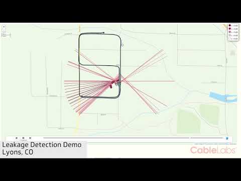
The CableLabs Proactive Network Maintenance (PNM) effort develops technologies and systems to proactively detect network problems before they impact the customer. In essence, our revolutionary technology turns every cable modem into a troubleshooting device, transferring that information to cable operators. Deploying PNM technologies results in faster and more accurate diagnoses of problems, faster repairs and ultimately a happier customer - all of which lead to lower costs for cable operators.
One of our PNM efforts tackles signal leakage and noise ingress.
The demonstration in our video is of an automatic data capture system that could be mounted on a vehicle that normally spends much of the day driving through neighborhoods, such as a garbage truck, a dry cleaning delivery service, or a taxi cab. The system can be completely automated to capture, upload, process and prioritize network maintenance. Watch our video below to learn more about this groundbreaking technology.
Don't forget to subscribe to our blog to stay current with our PNM effort.
Wireless
Getting Rid of a Big Communications Tax on OFDM Transmissions

You can find the background information for this article in the post "Sharing Bandwidth: Cyclic Prefix Elimination."
Most wireless transmissions use a modulation technology called OFDM (orthogonal frequency-division multiplexing). This method was invented by Saltzburg and Chen at Bell Labs in the 1960s, but was not widely commercialized until the 1990s when faster signal processing chips became available. This modulation method has now been adopted into DOCSIS 3.1 technology.
In essence, data symbols are formed into blocks comprised of a large number of cosine waves of differing magnitude and phase values. Because the waves all have an integer number of cycles in the block, they do not interfere with each other. That is, they have a mathematical property of orthogonality.
This modulation technique excels when there are a lot of reflections, a.k.a. multipath, echoes, or dispersion. For this modulation to be successful, a portion of the transmitted signal must be copied from the back and pasted onto the front of the transmitted block. This is illustrated in Figure 1. The copied and pasted signal is called a cyclic prefix (CP), or a cyclic extension, or sometimes a guard interval. The function of the CP is to allow any echoes to die out before the remainder of the block is analyzed.
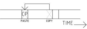
Figure 1: A cyclic prefix (CP) is made by copying a part of the end of a block and pasting it onto the front, providing immunity from echoes
While this modulation technique works well, the CP is pure overhead, a waste of expensive scarce bandwidth, and depletes battery power on wireless transmitters. A CP is a communications tax on both bandwidth and battery power and CP overhead generally ranges between 5 and 25%.
CableLabs Invention
CableLabs has invented a method to get rid of the CP using a math trick called an “overlapped circular convolution” to remove the effect of echoes without the CP. Parts of neighboring preceding and subsequent blocks are used as “pseudo-prefixes.” After equalization, the neighboring blocks pieces are discarded, leaving a de-ghosted block. Essentially the pseudo-prefix is applied at the receiver, and the transmitter doesn’t need to send any CP. That also means that the duration of the pseudo-prefix can be arbitrarily increased at the receiver for severe echo environments.
Figure 2 is a block diagram illustrating the CableLabs method, where a pseudo-prefix is created at the receiver using neighboring blocks. For wide-bandwidth applications, the overlapped circular convolution can be replaced with an overlapped Fourier transform with frequency domain equalization. This is more computationally efficient. For a user, the implementation of this technology means the cell phone data rates go up when receiving, and battery life is longer when transmitting.
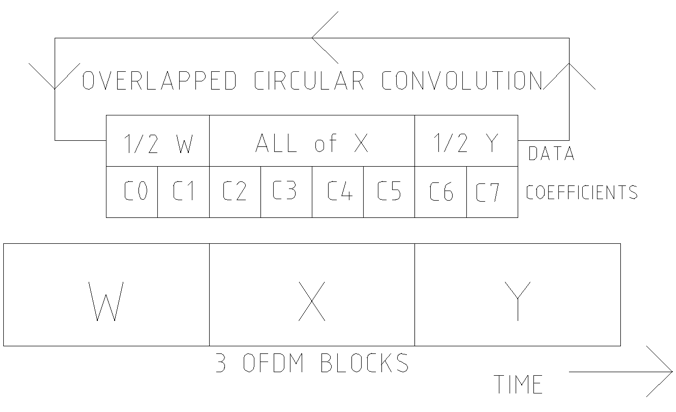
Figure 2: A “pseudo-prefix” for the X blocks is made with part of W block and part of the Y block. After equalization using an overlapped circular convolution, the partial blocks are discarded, leaving block X fully equalized. Next, the process is repeated to equalize the Y block.
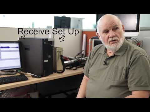
Watch the video below to learn more about cyclic prefix elimination:
A technical paper describing the technique in detail is available in the December issue of the SCTE ISBE Journal of Network Operations on page 42 titled "OFDM Cyclic Prefix Elimination." You can download a copy for free once you register on the site. Subscribe to our blog or contact Principal Architect Tom Williams for more information
Wireless
Sharing Bandwidth: Cyclic Prefix Elimination

Unfortunately, there is only so much over-the-air wireless bandwidth, and it must be shared between a lot of folks. And the situation is not getting any better. While you can usually run another wire or fiber optic cable between two locations to get more bandwidth, if you have a wireless application you must share this scarce resource.
New applications, such as IoT (internet of things), 3-D Virtual Reality headsets, and new cell phone applications are demanding more and more bandwidth. With cable subscribers watching video on portable devices, such as tablets and phones, interference problems (such as frozen pictures and tiling) are becoming more frequent problems. More than half of customer complaints are caused by wireless problems, and the most common problem is Wi-Fi interference, frequently from a neighbor’s service.
Solutions to the Problem
- One solution to the problem of more bandwidth is to use cellular technology and make the cell size smaller. Have you ever observed that out in the country cell towers are tall for a long reach? But in crowded cities, they are much closer to the ground, and the antennas are pointed downward. This is to reduce cell diameter in highly populated areas, allowing bandwidth reuse in non-overlapping cells. Transmitted power is also reduced for small cells to limit signal reach, thus reducing interference. However, large numbers of cell sites are expensive to deploy and maintain - and the bandwidth itself can be expensive. In the latest FCC bandwidth auction, the 600MHz band in the United States was sold for almost $20 billion!
- Other techniques to increase bandwidth include steerable beams and a technique called MIMO (multiple input, multiple output). This is a system for reusing the spectrum with more unique signals in the same air, by transmitting 2 or more signals on different antennas which are physically separated. At a receive site, sophisticated signal processing, using 2 or more antennas, separates the two signals.
CableLabs Innovation: Cyclic Prefix Elimination
CableLabs researchers are constantly looking for efficiency improvements, and they have found one way to improve wireless signals to make them use less bandwidth. This method, called “OFDM CP Elimination” (the full mouthful is Orthogonal Frequency Division Multiplex Cyclic Prefix Elimination!), allows the data to be sent in less time, increasing the resolution of pictures, and reducing the time for screen updates. Their method eliminates an overhead called a “Cyclic Prefix”, thereby improving efficiency by up to 25%. A side benefit of finishing transmissions earlier is increasing battery life for handheld devices.
Interested in a deep dive into cyclic prefix elimination? Check out my video on the subject, my blog post "Getting Rid of a Big Communications Tax on OFDM Transmissions" and my technical paper in the December issue of the SCTE ISBE Journal titled "OFDM Cyclic Prefix Elimination."
--
CableLabs innovates to help our member companies provide better services to their customer including higher data rates, higher reliability and lower latency. Subscribe to our blog to find out more.
Data
The Analog Monkey on Our Backs: Wrong-Thinking about Data over Cable

We inherit a lot of things from the past – not all of them good. When the telephone was invented by Elisha Grey, it evolved from wired telegraph lines. This was a natural evolution since the telegraph lines already existed and were proven, whereas radio technology was still in its infancy. When television was first introduced, it was radiated through the air to receivers in homes, as there were no cable systems initially, but radio broadcast by then had become a proven technology. However, this was not how the customers wanted to consume these services. When you are being entertained with pictures and sound you usually prefer to be seated. But when you want to talk to someone, you frequently are on the go. So due to technical constraints at the time, we ended up using a wired media for an ideally mobile product, and a wireless media for ideally sedentary product. This helps explains the marketing success of both cell phones and cable television.
As service providers, we are still adjusting the wired and wireless mix, and current technology is still influencing that adjustment.

Claude Shannon (1916-2001)
In 1947 Claude Shannon came along with a remarkable paper "Communication in the Presence of Noise" on the data capacity of a communications channel in the presence of random noise. He stated that the data capacity (C, in bits per second) of the channel is proportional to the bandwidth (B, in Hz) of the channel times log2(1 + signal power/noise power).
This brings up the question of what is the constraint on data capacity for any medium? If you want to increase the data capacity of a channel, is the channel lacking bandwidth, or is signal power constrained? The answer varies by medium. In wireless networks generally bandwidth is scarce. The US government sells it by the Hz, and it is very expensive. In fiber optic cable, signal power is usually required to be relatively low. A single mode fiber starts to go nonlinear at only about 10 milliwatts of power, but it has an enormous amount of bandwidth. On coaxial cable both power and bandwidth are constrained, and increased cable loss at high frequencies increases the noise power at higher frequencies. This is also true for telephony twisted pair, although the attenuation of twisted pair is much greater than coax. Cable’s capacity is not as constrained by Shannon’s Capacity Theorem as it is by common wrong assumptions, some of which are:
Assumption
We need to deliver analog TV signals at any frequency that the cable plant carries.
Reality
Not true. There is no requirement for analog TV delivery at 1.8GHz, which is the highest frequency supported in the DOCSIS® 3.1 specification. In fact, the requirement to deliver ANY analog TV signals is disappearing, or is already gone.
Assumption
4096 QAM is four times better than 1024 QAM.
Reality
Not true again. 4096 QAM transports 12 bits per symbol, and 1024 QAM transports 10 bits per symbol. So, 4096 has only 20% more capacity than 1024. But this 20% comes at an enormous price of 400% more required signal power. On the other hand, if you could somehow find 4X more bandwidth, you could use the same 4096 QAM signal power to transmit 400% more data. (Hint: look above 1GHz)
Assumption
In RF line amplifiers, steep up-tilts are required.
Reality
Not true again. This is a carry-over from analog TV delivery, and is no longer required in DOCSIS 3.1 networks. In fact, the optimal way to spend your signal power is explained in Shannon’s classic paper, in particular Fig. 8. It is now referred to as the water-pour method. For the water-pour method, basically, in bands with low noise, it is optimal to use a higher percentage of the available signal power, and in bands with high noise, it is optimal to use lower percentage of the available signal power. Besides, it is just not practical from a signal power standpoint to extend the up-tilt to 1.8GHz for analog TV delivery.
A technical paper on this topic has been published on the CableLabs website.
In conclusion, our networks are going all digital, the old requirements have changed, and there is a lot of additional data capacity available on cable networks. Data capacity can be accessed both by using higher frequencies and reallocating signal power more wisely.
Tom Williams is a Principal Architect at CableLabs.
DOCSIS
The Evolution of DOCSIS Proactive Network Maintenance (PNM)

All cable operators would like to find and fix problems quickly, hopefully before a customer experiences a problem.
Long ago, before the advent of DOCSIS, the cable plant was one-way downstream and operators waited for the customer to inform them that something was not working as intended, usually with a phone call. With DOCSIS and the advent of two-way communication, the reporting process became potentially easier, but without an operational support system, the fallback was still the telephone. The Cable Modem Termination System (CMTS) could, for example, know that a particular Cable Modem (CM) had dropped off-line, but without any software to discover the problem and report the event to an attentive OSS, the subscriber still had to pick up the phone and talk to a human. This situation became much less acceptable when the cable system also became the phone system, as well as an interactive video entertainment system.
Traditionally there have been about 8 base indicators for problems in a cable network. These include details such as excessive transmit power at the CM or low receive CM signal levels. There were also indicators for high packet or codeword errors, both at the CM and CMTS, and low receiver MER (modulation error rate, a measure of noise and interference in the signal). While these indicators are useful, they are deficient at telling an operator exactly what a problem is. For example, should a line technician or an installer be sent? Where should they go and what should they be told to check? In any case, high packet errors generally indicate a poor customer experience, if anyone is using the affected frequencies while the packet errors are occurring.
Hooks for cable operational support systems (OSS), which have traditionally used IPDR (Internet Protocol Detail Records) or SNMP (Simple Network Management Protocol) to relay DOCSIS MIBs (management information base) data, have been steadily improving, and are on a threshold of quantum improvements. In the early days, some of the MIBs were not sufficiently well specified or implemented to produce valuable data. That is rapidly changing.
The first MIB objects to be exploited for detailed intelligence about plant issues were upstream equalization coefficients. DOCSIS uses upstream linear pre-distortion at the CM so that a burst transmission, after it passes through network distortion, arrives at the CMTS clean. An analogy would be eyeglasses that pre-distort an image so that it arrives on your retina in-focus.
As an example, wiggles in the frequency response indicate standing waves generated by an echo tunnel. One or both ends of a severe echo tunnel locate a signal reflection caused by a damaged cable plant. The frequency of the standing waves can be measured to reveal the length of the echo tunnel, which indicates a line distance.
Further enhancements to the pre-distortion analysis technique allowed accurate grouping of common impairments affecting multiple CMs. If the network’s topology is known, a POI (point of interest) can be located on a map where the common impairment is likely located.
Another enhancement was the generation of a time-line for the small percentage of impairments that were intermittent. Figure 1 illustrates, with the top two plots, the upstream channel’s time and frequency graphs for a single CM from data taken over 3 days every 10 minutes respectively. The two colors of traces indicate that the connections were intermittent. The third trace indicates power variation with time and the fourth trace illustrates the variation in the upstream’s linear distortion. Generally while the connection was intermittent, more transmit power was required.
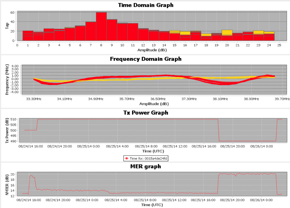
Figure 1 An intermittent CM observed over 3 days
A second valuable MIB object came from newer CM chips that could do full-band capture as part of their demodulation process. These chips allowed a full-band spectrum analyzer functionality to be provided by the CM. Figure 2 is a spectral plot from a CM.
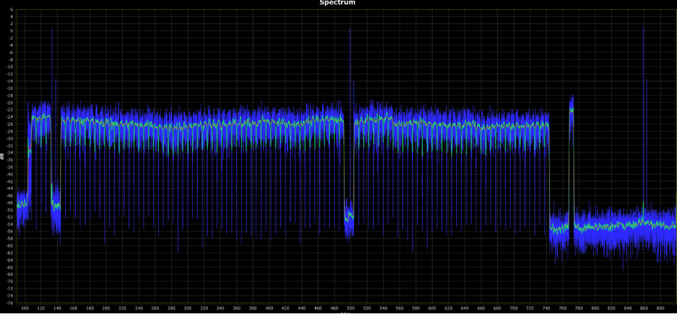
Figure 2 A full-band spectrum analyzer plot captured by a CM in the field.
Now, with some concerted and coordinated effort there is a potential for our diagnostic capabilities to take a big step forward with DOCSIS 3.1. Section 9 of the DOCSIS 3.1 PHY specification describes a powerful set of management objects that should allow more efficient plant maintenance. However, these benefits will not fall out of the sky. Careful coordination and collaboration will be required with the equipment vendors and cable operators to get the correct data sets into correct formats.
Other opportunities for big operational improvement also exist. For example, terminal devices can have an ability to generate their own complaints, even when the subscriber is not home. But terminal devices are only a component of a network.
Recognizing that the device closest to the subscriber likely knows the most about the subscriber’s experience, it is also possible to use the collective past experiences of several subscribers’ terminals to identify common problems affecting multiple subscribers, as well as problems affecting only one subscriber. This functionality could be stored in a common format log similar to a syslog.
In short, the future of cable OSS can be as bright as we are willing to make it – given lots of hard work, thanks to the management objects specified by DOCSIS 3.1.
Tom Williams is Principle Architect with the Network Technologies group at CableLabs. Tom’s main interest is in the physical layer of cable networks, and he enjoys digital signal processing (DSP), RF network design, and testing. He has been a cable engineer for 34 years.
Networks
Proactive Network Maintenance (PNM): Smarter Technology for Smarter Maintenance

We have always wanted more information about our world: Where is our next meal coming from; what’s the weather like; are my kids OK; did my team win? Past information delivery systems, such as the telegraph, the telephone, and broadcast television, have all been supplemented with the Internet. At a basic level, the Internet exists, in large part, to satisfy our appetite for information.
As Internet providers we need to keep that in mind, and determine when our service is not getting the job done. The term proactive network maintenance (PNM) describes the activities that assure the job of providing information is getting done – hopefully, before the customer becomes aware of any problem.
In the cable space the networks are diverse, expansive and non-obvious. I once heard someone state that anytime a subscriber complained, his company rushed to get a technician out to the house right away. Ouch! Without a network maintenance system, it’s a guessing-game where in the network the fault occurred. Chances are the wrong technician went to a wrong location with a wrong set of skills and wrong tools, and failed to get the repair job done. This is trouble for everybody (except maybe your competition). There will be a call-back, the subscriber is going to be dissatisfied, the technician is going to be judged as a failure by his supervisor, and the network fault continues to cause even more problems with other subscribers.
Cable services are delivered by systems, such as the video system, the DOCSIS system, and the IP phone system. Video systems are somewhat difficult to mine for data because of their proprietary nature, many generations of legacy STBs with differing capabilities, and bandwidth-limited data channels, called Out Of Band (OOB). But there are some good opportunities here.

For example, if a customer is watching a digital TV channel, and the box determines there are uncorrected code blocks, it “knows” that the customer is watching an impaired picture. A higher code block error rate means a worse picture. The customer should not have to get up and make a phone call when a connected box can do that automatically.
The DOCSIS system, on the other hand, has a pretty good set of handles to determine what is going on in the network. Most of the assurance traffic uses SNMP (simple network management protocol) and a fat pipe to relay all that data. Generally the assurance process starts with a lie: The operator asks what the cable modem’s health is, but the cable modem is usually fine – it’s the network that may be sick. And a sick network can affect many cable modems.
CableLabs has a proactive network maintenance effort that is developing systems to report if the network is getting the job done. The effort focuses on developing methods and tools around the existing data, developing new sources of data, and transferring information to member cable operators.
Proactive network maintenance results in faster and more accurate diagnosis of problems, faster repairs, happier customers and lower costs for cable operators.
You can find out more here.
Tom Williams is Principle Architect with the Network Technologies group at CableLabs. Tom’s main interest is in the physical layer of cable networks, and he enjoys digital signal processing (DSP), RF network design, and testing. He has been a cable engineer for 34 years.